Turbine growth and the higher risk of resonance excitations
Installations of turbine towers above 120m in hub height have more than doubled in the past 10 years. The demand for larger turbines continues to grow with larger turbines (3+ MW) growing in market share year over year. Offshore wind specifically is looking at more than 70% of orders for 5MW machines and larger. Both GE and Siemens have 10MW and larger machines currently in development and prototype testing.
Turbine original equipment manufacturers (OEMs) continue to pursue the development of larger wind turbines for increased power production. The reasons why are fairly obvious.
Taller wind turbine towers target improved performance with reduced wind shear. Larger rotors enable increased energy capture with larger swept areas. And softer wind turbine blades enable the targeting of lower wind speed sites. All of these design changes result in lowered component and system fundamental frequencies.
And therein lies a problem.
Mapping system frequencies
Larger turbine components tend to have lower fundamental frequencies due to their size, and these lower frequencies have an increased chance of coinciding with a turbine operating frequency. As system and component fundamental frequencies decrease, the likelihood of modal instabilities increases due to the coincidence with the rotor tower passing frequency. And with unstable resonance comes the very real risk of wind turbine damage.
Wind turbine designers use what’s known as the Campbell Diagram to map the relationship between system frequencies and rotor speed. The frequency of one full rotor rotation is known as the rotation frequency of the turbine (1P). A full rotor rotation for a three-bladed turbine consists of each blade passing the tower once. This frequency is known as the blade passing frequency and is three times the turbine rotation frequency (3P). Two full rotor rotations represent twice the blade passing frequency with six blade-tower passes (6P); three rotations is nine blade-tower passes (9P), etc. The point on a Campbell Diagram at which a component frequency crosses with a rotor speed multiple is known as the resonance point.
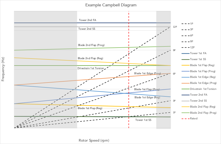
In worst-case scenarios, these crossings occur at rated rotor speed, which is the rotational speed at which rated nominal turbine power is produced. In essence, rated rotor speed is the rotational speed at which a turbine is designed to operate. In these cases, energy would be continuously loaded into the resonant mode during normal turbine operation at rated speed. Unless the condition is corrected, energy would load into the system until a failure occurs.
Larger turbines, larger risks
The example Campbell Diagram below illustrates the risk of lowered blade frequencies in larger wind turbines.
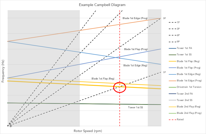
You can see that the Blade 1st Flap mode crosses the turbine rotation frequency (1P) close to rotor-rated speed (the vertical red dashed line). This represents the Blade 1st Flap mode being energized once per rotation at the given rotation speed. Stretching the turbine’s blade design with a longer (or softer) version can reduce the Blade 1st Flap mode. This moves the Blade 1st Flap frequency crossing with 1P to directly on top of the rated rotor speed. What this means is that as the wind turbine operates as designed at its rated RPM, energy will be continuously loaded into the Blade 1st Flap mode at the 1P frequency—building into the mode. If no corrective action is taken, this will eventually lead to blade damage or eventual blade failure.
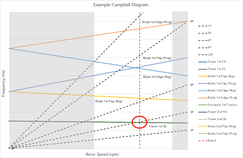
A similar risk occurs with taller, more flexible towers.
Below, you can see that the tower’s first fundamental frequencies (Tower 1st FA and SS) are at risk of crossing rated RPM with 3P. If this happens, the tower fundamental FA and SS modes are energized with each blade-tower pass, or three times per rotor revolution. It’s easy to imagine this would be extremely detrimental for both power production and the viable fatigue life of the turbine system.
Overcoming design challenges
Turbine designers must be aware of these frequency crossing points when designing wind turbine systems. They must fully understand the intended loading conditions and sites in which the turbine will be placed. That means designers must take special care when existing turbine platforms are grown (or stretched) to uprate power and/or target lower wind sites.
To be sure, there are plenty of risks that turbine designers must be aware of. But these design challenges aren’t insurmountable. With the right insights—and the right partners—you can better mitigate the risks of resonance expectations in wind turbine design and management.